FDM / FFF
Fused Deposition Modeling
FDM extrudes engineering thermoplastic layer by layer. It is the most economical process for functional prototypes, manufacturing aids and low-volume enclosures, with the widest material selection from PLA to carbon-fiber nylon.
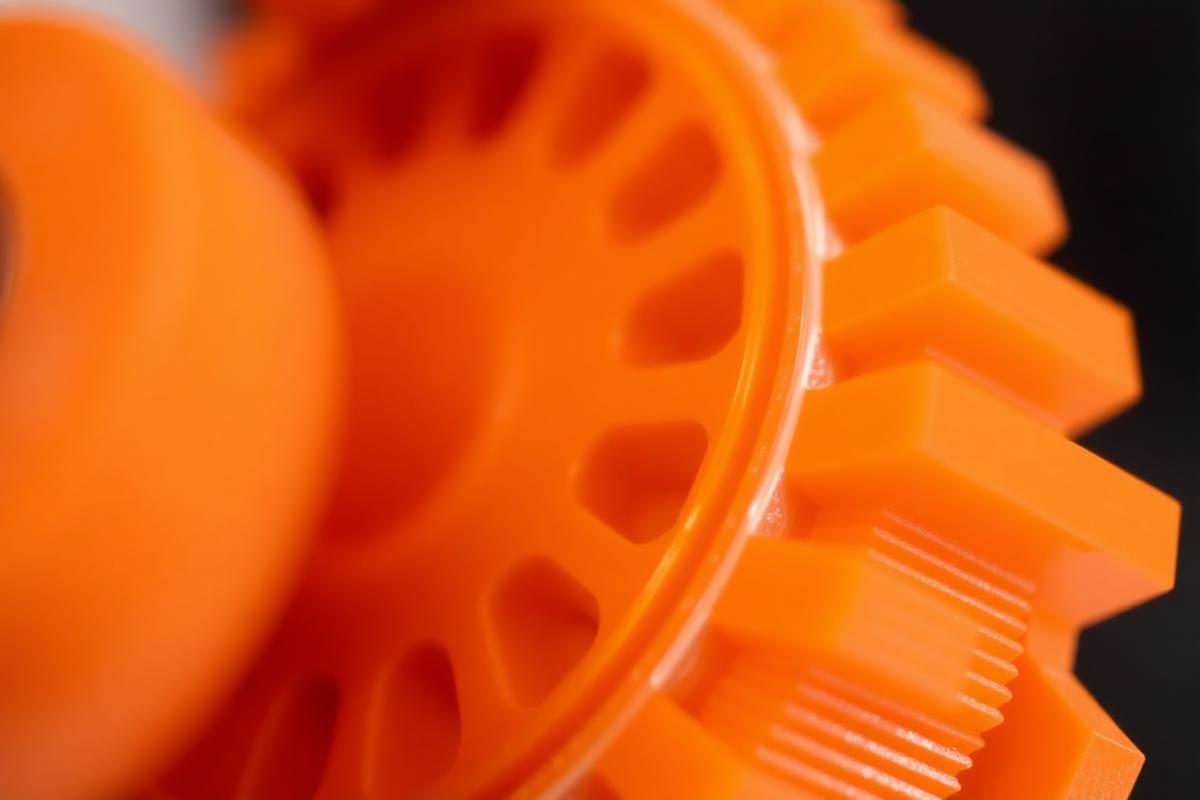 FDM / FFF · ± 0.2 mm typical
How FDM / FFF works
- 01
Filament is melted and extruded through a heated nozzle.
- 02
The toolhead deposits material along each layer contour.
- 03
Layers fuse as they cool; supports print where geometry overhangs.
- 04
Supports are removed and the part is optionally finished.
Strengths
- Lowest cost per part
- Widest material range
- Large build volume
- Fast turnaround
Limitations
- Visible layer lines
- Anisotropic strength
- Limited fine detail
Design rules for FDM / FFF
Full guidance in the interactive design guide.
| Minimum wall (unsupported) | 0.8 mm |
| Minimum wall (supported) | 0.6 mm |
| Minimum hole diameter | 2.0 mm |
| Minimum feature size | 0.6 mm |
| Moving-part clearance | 0.4 mm |
| Minimum embossed text | 2.0 mm height, 0.6 mm depth |
| Overhang threshold | 45° without support |
| Max build dimensions | 350 × 350 × 350 mm |
- Vertical holes print more accurately than horizontal holes.
- Orient load paths along the XY plane — layer adhesion is the weakest axis.
- Add 0.5 mm chamfers to bottom edges to avoid elephant-foot.
Compare with other processes
All technologiesSLA
High-detail resin parts with smooth, injection-molding-like surfaces.
± 0.1 mm typical · 300 × 335 × 200 mm
SLS
Strong, isotropic nylon parts with no supports — built for end use.
± 0.3 mm typical · 330 × 330 × 400 mm
MJF
Production nylon at scale with fine detail and consistent mechanicals.
± 0.2 mm typical · 380 × 284 × 380 mm